|
Heat producing power and control
components are being packaged in less space, increasing the
power densities in electronic and industrial equipment
enclosures. Computers, programmable logic controllers,
microprocessors, variable speed drives, power conversion and
storage devices have found their way into every industrial and
commercial environment.
The problem of dissipating the heat
generated to prevent premature failure or process shutdown can
be solved by several means. The surface area of the enclosure
itself may serve as a passive means to dissipate this heat,
providing the ambient conditions are below the desired enclosure
interior temperature and the internal heat load does not cause
an unacceptable rise in temperature. When this is not possible,
an active approach is necessary.
Open loop powered ventilation, or
closed loop cooling may be used.
Open loop ventilation uses ambient air to remove the heat, and
may consist of small muffin type fans that exhaust or supply an
electrical enclosure, at times with filters to prevent airborne
aerosols and dust from entering the enclosure. The fans have the
advantage of utilizing a minimum of enclosure space and will
move a substantial volume of air where flow is virtually
unimpeded. Cost and complexity is minimized. Where density of
components impedes airflow, packaged blowers or motorized
impellers may be arranged to operate against these higher static
pressures. With a rack enclosure, supplemental fan trays may be
used to spot cool or supplement other air-moving devices.
Where maximum internal enclosure
design temperatures cannot be maintained using open loop ambient
air cooling, closed loop devices need to be considered. Air to
air heat exchangers, water to air heat exchangers,
thermoelectric heat exchangers and air conditioning units are
able to cool a confined amount of air within an enclosure. Heat
is transferred to the respective devices' ambient side where an
air mover or water coil transfers the heat to the room or
outdoors.
Air conditioners and water to-air
heat exchangers provide the greatest capacity to transfer heat
in closed loop conditions. They have the unique ability to
maintain a lower than ambient temperature and reduce the
humidity within the controlled space. It is important to note
that enclosure design temperatures may exceed the ambient
temperatures, yet be below the electronic components' design
limits. Depending upon the NEMA enclosure type, which designates
the environmental hazard from which the contents are being
protected, an air conditioner can be provided to operate in most
locations. Locations subject to dust, dripping liquids, rain,
wash down and corrosive atmospheres can utilize these "Special
Purpose Air Conditioners".
A typical "Special Purpose Air
Conditioner" operates as follows. Heat is transferred from the
enclosure components by circulating air around and through them,
the air is then cooled, dehumidified and returned to the
enclosure without the admission of air from the outdoors. The
heat is removed from this air within the air conditioner and
discharged by means of a vapor compression refrigeration cycle.
This takes place in a hermetically sealed system, utilizing
either an air-cooled or water- cooled condenser coil. A
schematic of a typical Air Conditioner is illustrated (see
figure 1).
The compressor forces refrigerant,
in vapor form, into the condenser coil where it is cooled by
ambient air. As it cools, the refrigerant condenses into a
liquid, which is passed through a filter to remove impurities
and excess moisture. The liquid refrigerant flow is metered by a
thermostatic expansion valve or capillary tube, to control its
admission to the evaporator coil which is a part of the closed
loop on the inside of the enclosure.
The refrigerant enters the
evaporator as a liquid beginning to vaporize. As the blower or
fan driven heated air from the enclosure passes through the
evaporator coil, the heat is transferred to the refrigerant,
converting the refrigerant to vapor. High levels of humidity
present in the air are removed by condensation, the water is
drained to the outside and evaporated in some cases. This cool,
dehumidified air is then returned to the enclosure. After the
heat is transferred to the refrigerant in the evaporator, the
refrigerant passes into an accumulator, where any remaining
liquid is separated. The gas then returns to the compressor to
repeat the cycle in a continuous process.
Control of the system is generally
kept simple. When power is applied to the air conditioner the
evaporator blower starts and runs continuously. If the
temperature within the enclosure is high, the condenser blower
and the compressor turn on, operating until the thermostat
setting is reached. The thermostat is used as a low limit
setting. This is typically 75�F, the point at which the
compressor and the condenser fan or blowers are turned off. Air
within the enclosure continues to be circulated by the
evaporator blower or fan, picking up heat from the components
within the enclosure. The thermostat has a differential setting
that is typically 12-15 degrees above the low limit setting.
When the air circulated within the enclosure rises by this
amount, or at about 90�F, the compressor and condenser blower
turn back on reducing the enclosure internal air temperature
once again. Therefore, at start up of an enclosure system, it
would be normal for the internal temperature to rise to this
temperature before the refrigerated cooling would begin. As the
air cools, a balance of temperature within the enclosure is
reached, ideally the compressor and condenser fan continue to
run most of the time until the heat load changes.
It is important to
understand that enclosure cooling is not "comfort
"cooling as found in homes and buildings. Heat producing
power and control components are typically limited to
maximum enclosure air temperatures of 100�F to 110�F.
The actual component surface temperatures are higher.
Maintaining enclosure temperatures too low often becomes
problematic. Condensation may form on live electrical
surfaces if their temperature falls below the dew point
of the air. Subsequent corrosion or electrical safety
becomes a serious issue.
Various control features
are available to operate in cooler ambient conditions
found outdoors or in poorly heated settings. Compressor
short cycling controls may be added to prevent damage
caused by frequent starting when heat loads fluctuate.
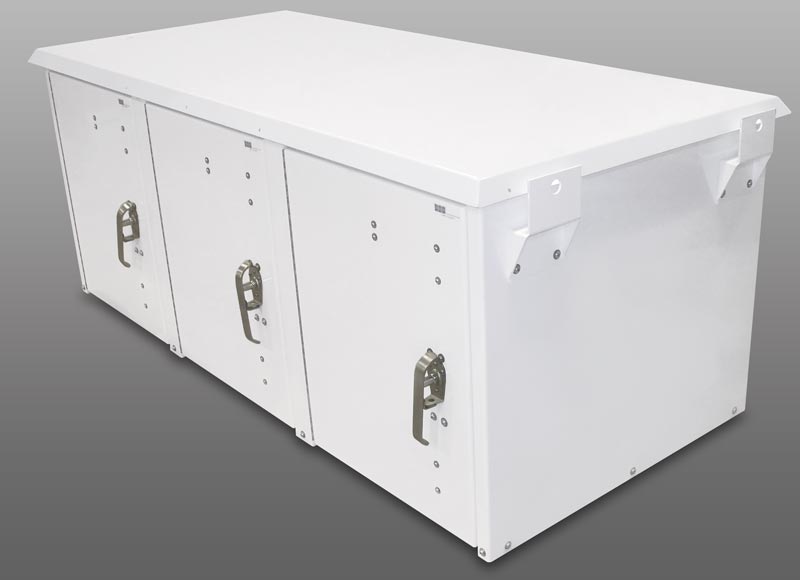
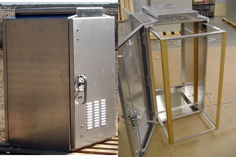
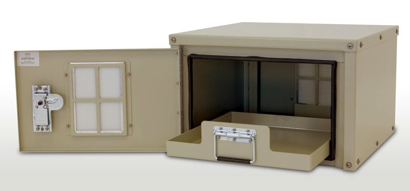
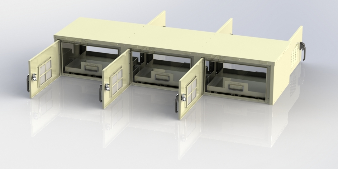
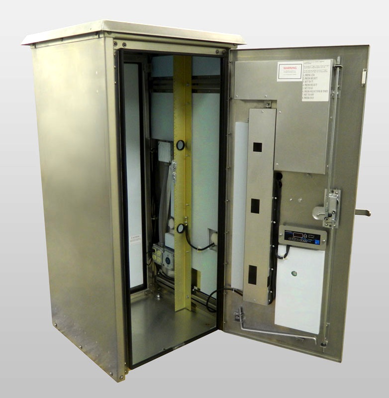
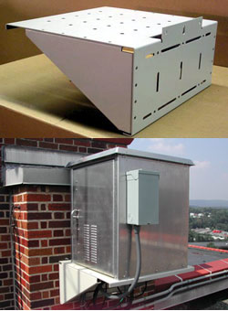
The air conditioner
typically carries an agency marking such as UL,
Underwriters Laboratories which designates the
environmental hazard from which the contents are being
protected. This marking should be matched to the
enclosure to be cooled. Typical examples include NEMA
12, (indoor use, protection from dust and dripping
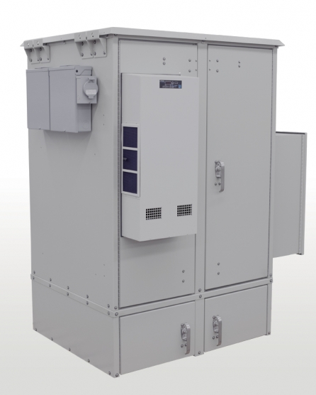
liquids) (see Figure 2), NEMA 3R, (outdoor use and rain
proof) (see figure 3) and NEMA 4/X (outdoor or indoor
use, protection from wash-down and corrosive
environments) (see figure 4).
Sizing calculations for the
selection of an air conditioner are accomplished with
ease via software available on manufacturers' websites
or on available software copies. The internal heat load
is determined based upon measurement or estimation.
Enclosure surface area, desired maximum internal
enclosure temperature, degree of thermal insulation if
any, ambient temperature and for outdoor use, solar load
are used to determine the total heat load in BTUH. It is
important to note that the solar load and the degree of
insulation can become very significant. Entering a
closed automobile after it has sat in the hot summer sun
illustrates this point.
For best results be careful
not to oversize the unit. Be certain that both the
evaporator and condenser air flow paths cannot short
circuit, or are impeded. Be cautious of adding
protective covers to the outside of the unit which may
reduce air flow and unit thermal performance. Seal the
electrical enclosure to prevent humidity and outside air
from entering. Closed loop enclosure cooling is the
goal. Consult performance data, or contact the
manufacturer for temperature conditions other than the
rating points shown in most catalogs. Typical
performance is shown in figure 5. A properly sized, well
designed system, free of refrigerant leaks, with a
stable power supply will cool critical systems trouble
free for many years.
Should you have any
technical questions please contact us
 |