BASIC COOLING
METHODS Forced Ventilation Air Cooling
|
BASIC COOLING METHODS
By
Kooltronics
Forced Ventilation Air Cooling
In clean,
non-hazardous environments with
acceptable ambient temperatures, a
simple forced-air cooling system
utilizing ambient air is usually
adequate. Combined with a low-cost
air filter, such devices generally
meet the heat removal needs of
typical electronic and electrical
equipment (Fig. 1).
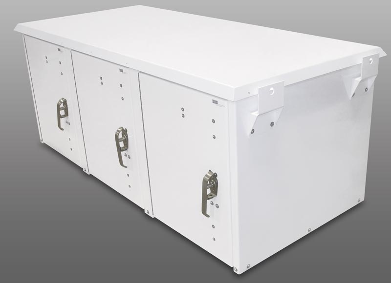
FIGURE 1
 Fans,
Packaged Fans, and Centrifugal
Blowers can be used to pressurize or
exhaust cabinet air. The ambient air
should be filtered before it enters
the cabinet.
Fans,
Packaged Fans, and Centrifugal
Blowers can be used to pressurize or
exhaust cabinet air. The ambient air
should be filtered before it enters
the cabinet.
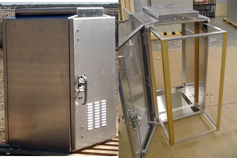
 Packaged Blowers mount to the
internal cabinet mounting rails.
They are used to pressurize the
cabinet and provide filtered ambient
air.
Packaged Blowers mount to the
internal cabinet mounting rails.
They are used to pressurize the
cabinet and provide filtered ambient
air.
IF AMBIENT COOLING AIR CAN
BE USED AND THE SYSTEM HAS
LOW STATIC PRESSURE
USE A FAN
|
IF AMBIENT COOLING AIR CAN
BE USED AND THE SYSTEM HAS
HIGHER STATIC PRESSURE
USE A BLOWER
|
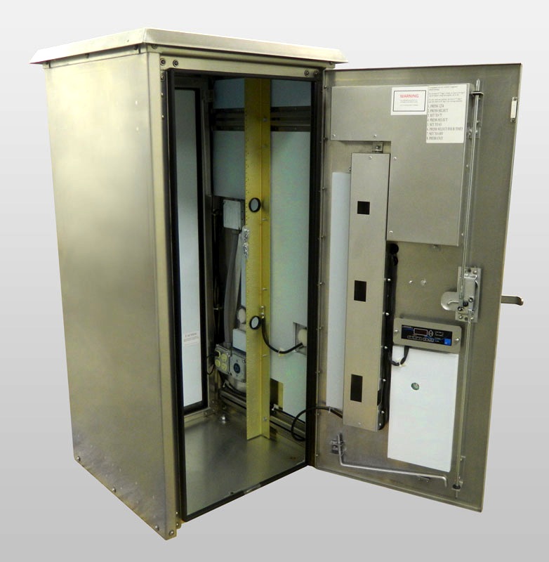
Closed-Loop Cooling
In
harsh environments involving high
temperatures, heavy particulates,
oil, or chemicals capable of
damaging components, ambient air
must be kept out of the enclosure.
Sealed enclosures are generally
used, with closed-loop cooling
consisting of two separate
circulation systems in a single
unit. One system, sealed against the
ambient air, cools and recirculates
the clean cool air throughout the
enclosure. The second system uses
ambient air or water to remove and
discharge the heat.
IF INTERNAL CABINET
TEMPERATURE CAN BE GREATER
THAN THE AMBIENT AIR
USE A HEAT EXCHANGER
|
IF INTERNAL CABINET
TEMPERATURE MUST BE EQUAL TO
OR LOWER THAN THE AMBIENT
AIR
USE AN AIR CONDITIONER
|
A
comprehensive discussion of
Closed-Loop Cooling appears later in
this Design Guide. |
|
FILTRATION
Filtration of contaminated air can be
accomplished in some installations to permit
forced convection cooling of electronic
equipment. Generally, contamination can be
broken down into two major categories:
airborne particulate matter and corrosives.
In most cases, particulate matter can be
filtered out and the air made safe for the
cooling of heat-producing equipment.
However, removal of corrosives by filtration
generally requires processes that are too
costly and/or too airflow restrictive.
Therefore, isolation of the enclosure
contents is usually necessary.
Careful consideration must be given to the
type and severity of the conditions to be
encountered. Filters must be able to protect
the enclosure at the worst-case level of
contamination anticipated. Once the system
is installed, adequate preventive
maintenance is crucial. Filters must be
cleaned or replaced regularly, or means must
be provided for continuous monitoring of the
filter condition.
In order to prevent choking of airflow, it
is important for the filter inlet opening to
be at least as large as the total area of
all air outlets. Inlet and outlet areas
should be determined after allowance for
impedance of grille materials or other
barriers.
Air inlets and outlets should be as far
apart as possible, so the air is forced to
circulate through all heat-producing
components. All air inlets should be
filtered, whether the air enters through a
fan or blower, or directly into the cabinet
for exhausting, when pressurization is not
feasible.
STANDARD FILTERS
Filters used with typical electronic
equipment cooling devices are usually the
viscous-impingement type and are
approximately 65% efficient. They utilize
fibers that have been coated with a
nondrying, tacky substance which traps
particulates as air is drawn through.
Usually constructed of aluminum foil or
flock- coated pleated wire screen, the
filters can be cleaned, recoated and re-used
indefinitely. Often, filters of this type
are used as prefilters in multiple filter
systems to extend the service life of high
efficiency or absolute filters.
HIGH EFFICIENCY FILTERS
High efficiency or absolute filters are
available in efficiencies ranging up to
99.97% on 0.3 micron size particles. The
filter media is a pleated paper which
operates as a strainer, since its openings
are physically smaller than the particulates
it is designed to intercept. This type of
filter offers relatively high resistance to
airflow and is employed only where more
common filter types are incapable of
providing acceptable levels of protection.
In applications where such filters are
required, provision must be made for
adequate airflow to overcome the higher
resistance in addition to the cooling
airflow needed.
FLOW MONITORS
Where higher levels of contamination exist
or can develop rapidly, filtered cooling air
packages should be equipped with some form
of flow monitor. In the event of a reduction
in air delivery below a minimum acceptable
level due to a clogged filter, a
flow-sensing or temperature-sensing device
triggers warning alarms or shuts down
affected equipment.
Pressure differential switches, which
respond to pressure drops across an air
filter, are often employed, as are simple
vane-type airflow velocity sensors or
thermostatic over-temperature detectors
located at equipment hot spots. At times,
flow- and temperature-sensing devices are
employed in combination. In this way,
relatively low airflows are accepted when
the ambient temperature is low.
At higher ambient temperatures, reduced
airflow, resulting in excessive component
temperature, activates the warning device or
shuts off power. This arrangement permits
maximum filter utilization and safety to the
equipment.
The need for flow monitoring should be
evaluated carefully because of the added
cost of the various devices required.
VARIABLE SPEED BLOWERS
The optimum open-cycle system for use in
contaminated environments combines
appropriate air filters and cooling-effect
detectors with a variable speed blower that
adjusts its operating speed to provide the
desired cabinet air temperature, as sensed
at some point within the enclosure. Since
blower air delivery is directly proportional
to motor shaft speed, airflow rate can be
adjusted to a minimum compatible with a
clean air filter and low ambient
temperature. Should ambient temperature
increase or the filter clog with
contaminants, the sensor and controls would
demand an increase in motor speed until the
new conditions were satisfied.
The variable speed blower is self-adaptive
to changes in ambient temperature, air
density, line voltage, power dissipation in
the enclosure, and to the degree of
filter-loading. Since the blower operates at
the minimum speed and air delivery
compatible with cooling, both power
consumption and the rate of contaminant
accumulation on filter surfaces is greatly
reduced, compared to a constant speed blower
designed to satisfy worst-case conditions.
This increases filter life and reduces
filter maintenance to a minimum. Conversely,
as the filter loads, blower air delivery
could increase to levels beyond those that
would be obtained under constant speed
conditions. Again, cost must be considered.
|
CORROSIVE ATMOSPHERES
Corrosive environments, such as those found
in chemical plants and in industries where
processes result in harsh chemical
by-products, usually preclude the use of
filtered ambient air for forced convection
cooling. Corrosives generally cannot be
filtered out by normal filtration methods,
and scrubbing techniques that must be used
to rid air of corrosives are complex,
costly, and often not satisfactory.
For such applications, the cooling method
requires isolation of the sensitive
components subject to damage from the
offending substances. The solution is
usually closed-loop cooling - Heat
Exchangers or Air Conditioners which
consists of two separate circulation systems
in a single unit. One recirculates clean
cooling air through the electronics within
the sealed enclosure, while the other
discharges the heat removed from the cabinet
to the ambient air or into water for
removal.
If the corrosive atmosphere is normally
within an acceptable temperature range,
air-to-air Heat Exchangers can be used to
provide cooling for equipment enclosure.
When both high ambient temperatures and
corrosives are present, either Air
Conditioners or water-to-air Heat Exchangers
must be employed to cool the hot components.
Regardless of the cooling apparatus chosen,
it must be constructed of appropriate
corrosion-resistant materials, or be treated
with corrosive-resistant coatings, to ensure
long, trouble-free operation under the
conditions to be encountered.
Care should be taken to review the
particular conditions involved. In most
cases, a system can be designed to meet
specific requirements at moderate cost.
|
|
CLOSED-LOOP COOLING
Many applications using
sophisticated electronic/electrical
components require a closed-loop
cooling system to dissipate heat
buildup without introducing outside
contaminated air. Closed-loop
cooling is required when equipment
is operated in hostile environments
containing dirt, oil, humidity or
corrosives, which adversely affect
the performance or ultimate survival
of the components. The presence of
airborne particulate matter
compounds the difficulty of
controlling the temperature of the
equipment in the enclosure.
HEAT EXCHANGERS
For installations that can operate
at above-ambient temperatures, Heat
Exchangers provide moderate-cost
closed-loop cooling. Available in
both air-to-air and water-to-air
versions, there are models covering
a wide range of cabinet sizes and
performance capacities. Depending
upon the model selected and the heat
load, near-ambient to
moderately-above-ambient
temperatures can be achieved.
For applications that can utilize
Heat Exchangers, the advantages
compared with Air Conditioners
include:
-
Lower initial cost
-
Lower power consumption
-
Simpler construction
-
Fewer operating components
-
Lighter weight
AIR-TO-AIR HEAT EXCHANGERS
Advanced air-to-air Heat Exchanger
designs for cooling enclosures
include two types of heat transfer
methods. One design consists of a
finned-tube coil which contains
liquid refrigerant. The warm air
exhausted from the equipment cabinet
to the Heat Exchanger is directed
past the coil, causing the
refrigerant to boil and absorb heat.
The resultant refrigerant vapor
rises to the upper portion of the
tubes, where the heat is removed by
the cooler ambient air and the
refrigerant condenses back to
liquid, completing the cooling cycle
in a continuous process.
The most recent developments in
enclosure Heat Exchanger design
employ high-efficiency heat transfer
elements fabricated of embossed
convoluted metal foil or thin-film
polymer material, constructed into
two totally separate air paths. The
air leaving the hot enclosure is
directed through one side of the
exchanger, where the heat passes
through the element walls into the
ambient-side airstream and is
dissipated.
Figure 3 illustrates heat transfer
in air-to-air Heat Exchanger
applications.
WATER-TO-AIR HEAT EXCHANGERS
If ambient air
cannot be utilized directly as a
cooling medium, another
cost-effective method of cooling is
a water-to-air system (Fig.4). Water
is used to remove heat from air
circulated within the electronic or
electrical enclosure.
Cooling water is
circulated through a finned-tube
coil, which is installed in a
compartment isolated from the
enclosure to protect the contents
from possible leakage of water. As
the heat-laden air circulates
through the coil, the heat is
absorbed by the water and carried
away, in a continuous process.
Water-to-air
systems are easy to install and
usually require minimum maintenance.
The water used must be reasonably
clean and cold enough to ensure
proper operation of the cooling
system under the most severe
anticipated conditions.
In cases where
sufficiently cold water is
available, below ambient-temperature
cooling can be achieved. |
|
|
AIR
CONDITIONERS
Air Conditioners
are required where the equipment
operating temperature must be kept
at or lower than the ambient room
temperature, and/or the cabinet must
be sealed from oil, dust, fumes and
other contaminants.
Specially packaged
vapor compression Air Conditioners
(Fig. 5) protect the components and
furnish the required cooling. Such
Air Condition-ers employ hermetic
refrigeration systems with
additional controls. They provide
enclosure and air-path geometries
for direct installation to the
equipment cabinet and accomplish the
following:
- Isolate the
interior of the equipment
enclosure from ambient
conditions
- Cool the air
within the enclosure to the
optimum temperature for the
sensitive components
- Circulate the
air within the enclosure to
equalize temperature and
increase heat transfer from hot
components
- Automatically
vary cooling rate to maintain
close control of equipment
temperature
- Reduce
humidity harmful to sensitive
components
Air Conditioners that
are used to cool enclosed equipment
differ radically from room Air
Conditioners. In the area of
temperature control, for example,
most electronic systems are
adversely affected by large line
transients typical of Air
Conditioner compressor cycling.
Electronics also exhibit sensitivity
to electromagnetic interference
caused by thermostat contacts. The
control system of an Air
Conditioning package must be
designed accordingly.
In addition, the
field experience of many compressor
manufacturers has indicated that the
frequent start/stop cycling, typical
of standard Air Conditioner
operation, shortens compressor life.
These factors have
led to the develop-meant of
techniques for close control of
internal temperature over a wide
range of ambient conditions, without
turning the refrigeration compressor
on and off and without employing
electrically-controlled solenoid
valves.
All temperature
control for KOOLTRONIC Air
Conditioners is accomplished by
means of proportioning valves
activated by pressure signals within
the Air Conditioner hermetic system.
Generally, load temperature can be
controlled to �5�F over a range of
power dissipation, without the use
of thermostats. Frequent start/stop
cycling of the compressor is
eliminated, thus assuring longer
compressor life.
Recent
developments in temperature
requirements for enclosed components
has led to the addition of
adjustable Low Temperature Control
thermostats in all KOOLTRONIC Air
Conditioners to prevent
over-cooling. EMI/RFI suppressors
are included to control the line
transients associated with
compressor cycling and thermostat
operation.
Hermetic Air
Conditioners are available in
air-cooled and water-cooled models.
AIR-COOLED AIR CONDITIONERS
Heat removed from
the enclosure containing hot
components is discharged by
circulating the ambient air through
the condenser coil and returning the
heated air to the ambient. There are
vertical and horizontal types for
exterior mounting to side panels,
doors, or the top of the enclosures,
and for various internal positions.
WATER-COOLED AIR CONDITIONERS
Intended primarily
for extreme operating conditions of
high-ambient temperatures or severe
contaminants, these units utilize
water as the medium for heat
dissipation. The heat is absorbed by
cool water circulating through a
coaxial condenser coil, following
which the heat-laden water is
discharged or recalculated after
cooling |
|
|
VAPOR
COMPRESSION CYCLE
Heat is removed by
enclosure Air Conditioners and
discharged by means of the vapor
compressor refrigeration cycle. This
takes place in a hermetically sealed
system, utilizing either an
air-cooled or water- cooled
condenser heat exchanger. A
schematic ofa typical Air
Conditioner is presented in Figure
6.
The compressor
forces refrigerant, in vapor form,
into the condenser heat exchanger,
where it is cooled either by ambient
air, driven between the fins by a
specially engineered blower, or by
cool circulating water. As it cools,
the refrigerant condenses into
liquid, which is passed through a
filter to remove impurities and
excess moisture. The liquid
refrigerant flow is metered by a
thermostatic expansion valve or
capillary tube, to control its
admission to the evaporator.
The thermostatic
expansion valve is a feedback control
device which regulates refrigerant
flow on the basis of conditions
sensed at the evaporator outlet. The
capillary tube is a long,
small-diameter tube which employs
pressure differential and complex
two-phase internal flow dynamics to
meter refrigerant to the evaporator.
The refrigerant
enters the evaporator as a liquid
beginning to vaporize. As the
blower-driven heated air from the
enclosure passes through the
evaporator heat exchanger,
the refrigerant absorbs the heat and
the conversion to vapor is
completed. Any moisture present in
the air is removed by condensation.
This cool, dehumidified air is then
returned to the cabinet.
After the heat
absorption phase, the refrigerant
passes into an accumulator, where
any remaining vaporized liquid is
separated. The gas then returns to
the compressor, to repeat the cycle
in a continuous process.
The total heat
rejected at the condenser is all of
the heat entering the system from
the enclosure at the evaporator heat
exchanger, heat of compression and
heat rejected by the compressor
motor, since the compressor is
cooled by the refrigerant gas
returning from the evaporator.
Typical air
temperatures during the cooling
process are: cooled air to
enclosure, 75�F; heated air returning
from enclosure, 100�F; ambient air
cooling condenser,105�F; air
rejected from condenser, 140�F.
TEMPERATURE CONTROL
Typical
refrigeration and Air Conditioning
systems control temperature by
on/off compressor cyclingas air
temperatures fluctuate between
minimum and maximum thermostat
settings. Compressor start-up often
introduces substantial transients
into the circuit powering the
equipment to be cooled. Thermostat
or relay operation results in
electromagnetic inter- ference. Both
of these factors can adversely
affect
the function of electronic
equipment. On/off compressor control
necessitates choosing between large
temperature excursions or frequent
compressor cycling.
Furthermore,
frequent start/stop operation exposes
internal compressor components to
electrical and mechanical strains not
encountered during continuous
operation. The use of
electrical controls to handle high
compressor start-currents results in
eventual erosion of the control
contacts themselves.
In order to
eliminate the possibility of these
problems, KOOLTRONIC Air
Conditioners feature a
continuously operating compressor and
non-electric proportional control
system, which result in more stable
equipment temperatures and prolonged
life for the compressor and the
control system. Both blowers and the
compressor start simultaneously with
the application of power to the
unit, and continue to operate until
power
is removed at the time of equipment
shutdown.
The control bypass
valve, shown in Figure 6, permits
refrigerant, in gas phase, to be
injected at the inlet to the
evaporator heat exchanger. This
high-temperature, high-energy gas
presents an artificial heat load and
permits the effective cooling rate to
be varied as necessary to maintain
essentially constant temperature of
the air returned to the enclosure.
(It is normally factory set to
deliver air at approximately 70�F.)
This control also prevents
evaporator freeze-upsdur-ing periods
of low heat load or low ambient
temperature.
Although the
above control system works
effectively at most times, there are
instances of over-cooling due to low
heat load or low ambient
temperature. In order to prevent
that condition, Low Temperature
Control thermostats and EMI/RFI
suppressors have been added to all
KOOLTRONIC Air Conditioners.
When activated,
the Low Temperature Control shuts off
the compressor and condenser
(ambient side) blowers. The
evaporator (enclosure side) blowers
continue to circulate the air
through the enclosure and Air
Conditioner. When the air
temperature again reaches the level
at which cooling is needed, the
compressor and condenser
blowers r�sum� operation.
AMBIENT TEMPERATURE RANGE
Most KOOLTRONIC
Air Conditioners are designed to
operate at ambient temperatures
ranging from 50�F to131�F. Optional
Low Ambient Kits allow operation in
ambient temperatures as low as 0�F.
Maximum operating
ambient temperature decreases
linearly with altitude at the rate
of 3�F per1,000 feet between 2,500
and 7,500 feet, where maximum
operating ambient temperature is
110�F. The ability to operate at
high ambient temperatures permits
KOOLTRONIC Air Conditioners to be
installed in close proximity to
furnaces and other heat-producing
equipment.
For applications
in ambienttem-peratures higher than
the rated
maximum, consultation with the
KOOLTRONIC Engineering Depart-ment
often provides the solution.
CONDENSATION
High ambient
relative humidity does not affect the
rated capacities of KOOLTRONIC Air
Conditioners. They're designed for
installation on reasonably tight
enclosures of relatively limited
internal volume.
Normally, only
sensible heat loads are imposed on
the Air Conditioner. Even at an
ambient temperature of 95�F and a
relative humidity of 100%, the air
within a typical electronic
equipment
enclosure 21/2 feet square and 6
feet high will contain only small
amount of water in vapor form. As
the temperature of the air
being circulated within the enclosure
is reduced from 95�F to 70�F,
theater will be condensed quickly
in the evaporator heat exchanger and
be disposed of through the drain in
the condensate tray at the bottom of
their Conditioner.
Unless the
enclosure is totally sealed, some
slow invasion of ambient air will
take place through cracks and seams
in the cabinetry and the front
panels. However, even at
ambient relative humidifies of 100%,
the infiltration rate is normally so
small that the effect on cooling
capacity of latent heat of water
vapor condensation in the
infiltrating air
is negligible.
Cooling
performance of the Air Conditioner is
reduced if its capacity is used for
the condensation of excessive
moisture. This occurs if the
enclosure is poorly sealed oris open
for long periods, under high
humidity conditions. A
continuous flow of condensate denotes
that these adverse conditions are
present and should be remedied
immediately. |
|
|
SIZING CLOSED-LOOP COOLING EQUIPMENT
In forced
convection cooling of enclosures,
cooler ambient air is drawn or
forced through the components in an
enclosure and discharged. When
electronic/electrical enclosures are
sealed to keep out moisture, dust,
dirt and other contaminants, the
heat generated by the components is
trapped and closed-loop cooling (air
conditioner or heat exchanger) is
needed to maintain the optimum
environment for the components.
The heat generated
by the components is the INTERNAL
HEAT LOAD. Because of the internal
heat being generated, there is
typically a temperature differential
between the inside and the ambient
air outside the enclosure. Heat is
conducted through the exposed area
of the enclosure from the warmer to
the cooler space, and is known as
the HEAT LOAD TRANSFER. Since Air
Conditioners cool to below ambient,
the Heat Load Transfer is a heat
gain into the enclosure, whereas
it is a heat loss out of the
enclosure when Air-to-Air Heat
Exchangers are used because they do
not cool to below the ambient.
When sizing an Air
Conditioner or Heat Exchanger using
the methods on the following pages,
if the Internal Heat Load (in Watts
or BTU/Hr.) is known, it is the
value used in Step One. When
it is not known, there are several
methods of estimating, including (1)
Component Rated Heat Production;
(2) Air Flow Heat Rise; (3) Sealed
Enclosure Temperature; (4)
Incoming-Outgoing Power; and (5)
Component Efficiency. Of these, the
most accurate and least
time-consuming is Method (3), which
is the method we recommend for
uninsulated enclosures.
The following
steps should be followed:
(A) The Enclosure
must be operating at its highest
work load.
(B) All openings are sealed and
air-moving equipment turned off.
(C) Measure the inside air
temperature near the top of the
Enclosure.
(D) Measure the ambient air
temperature and determine the
differential.
(E) Calculate the exposed
surface area of the Enclosure
(sides and top) in square feet.
(F) Refer to the Temperature
Differential Heat Gain/Loss
Chart, at the temperature
differential determined in (D)
and multiply the Watts/Square
Foot by the exposed area (E).
This is the approximate
Internal Heat Load in Watts.
For BTU/Hr, multiply by 3.413.
The Heat Load
Transfer calculations required are
provided in Steps Two and
Three under Heat Exchanger
Sizing and Selection or
Air Conditioner Sizing and
Selection.
TEMPERATURE DIFFERENTIAL HEAT
GAIN/LOSS CHART
FOR
UNINSULATED ENCLOSURES
|
|
|
AIR CONDITIONER SIZING AND SELECTION
Air Conditioners for cooling
electronic/electrical enclosures
should be selected to provide
adequate cooling for the anticipated
worst-case conditions. For best
results, Panel-Mounted Air
Conditioners should have the
cool air inlet at or below the
lowest significant heat-producing
component and the return air port
should be above the highest such
component.
The capacity (BTU/Hr) should be
approximately equal to the Internal
Heat Load plus the Heat Load
Transfer (see Sizing Closed-Loop
Cooling Equipment), but should not
be over-sized, as this will result
in excessive cooling which may
affect component performance or
cause “sweating” of the Enclosure
during high humidity conditions.
Normally, no additional provision is
needed for the humidity in the
Enclosure at start-up because it
will be dissipated very quickly from
a properly-sealed Enclosure.
A
determination should be made of the
appropriate mounting position—side
panel, door, internal or top.
Although most KOOLTRONIC Air
Conditioners are equipped with
Condensate Evaporators (or are
available as an option) and all have
condensate drains, it is preferable
to not place an Air Conditioner
directly above electronic/
electrical components if the
application is likely to be subject
to high humidity, which will
infiltrate an imperfectly sealed
cabinet.
The
maximum allowable internal cabinet
temperature (Ti) should not exceed
the heat tolerance specification of
the most sensitive component in your
system.
NOTE: This selection process
applies only to indoor gasketed
enclosures which are uninsulated.
Before proceeding, read Sizing
Closed-Loop Cooling Equipment.
For applications involving outdoor
locations, solar load, non-metallic
or insulated enclosures, consult
KOOLTRONIC for assistance.
The model numbers of KOOLTRONIC Air
Conditioners reflect the
refrigerant, as of the publication
date. A 4 between the A and C
signifies R134a; a 3 signifies R22.
The Technical Data shown is as
determined by testing for UL
certification. As more R134a-type
compressors become available, R22
units will be redesigned for R134a
which may affect performance.
TO DETERMINE REQUIRED AIR
CONDITIONER CAPACITY
|
|
 |
|
AT EXCHANGER SIZING AND SELECTION
The proper selection of a Heat
Exchanger is determined by how many
WATTS can be dissipated at a given
temperature differential. Since a
Heat Exchanger uses ambient air or
available water for cooling, the
enclosure cannot be cooled below a
temperature slightly above that of
the air or water entering the Heat
Exchanger. Therefore, the greater the
temperature differential, the higher
the capacity of the Heat Exchanger.
Consequently, the smaller the
temperature differential required in
an application, the higher the
capacity of the Heat Exchanger
needed to achieve it.
The amount of heat to be dissipated
is the Internal Heat Load less
the Heat Load Transfer (heat
conducted through the uninsulated
walls of the enclosure).
The performance of Heat Exchangers
is expressed in WATTS/�F. In the
preferred “Air In” method, the
Watts/�F depicts the amount of heat
the Heat Exchanger is capable of
dissipating per degree Fahrenheit of
temperature differential between the
entering air or water temperature
and the maximum allowable internal
enclosure temperature. The
calculation process requires (a) the
amount of heat to be dissipated, (b)
entering air or water temperature,
(c) maximum allowable internal
enclosure temperature and (d) the
dimensions of the enclosure.
The maximum allowable internal
cabinet temperature (Ti) should not
exceed the heat tolerance
specification of the most sensitive
component in your system.
NOTE: This selection process
applies only to indoor gasketed
enclosures which are uninsulated.
Before proceeding, read
Sizing Closed-Loop Cooling
Equipment. For applications
involving outdoor locations, solar
load, non-metallic or insulated
enclosures, consult KOOLTRONIC for
assistance.
TO DETERMINE REQUIRED HEAT EXCHANGER
PERFORMANCE IN WATTS/�F—Air In
Method
This is the rating (Watts/�F Air In)
based on the temperature of the air
into the heat exchanger, after
exiting the hottest area of the
enclosure. Refer to the Heat
Exchanger Index and Selection Guide
for the unit that most nearly
matches the required performance and
dimensions.
Another rating, (Watts/�F Air Out)
is based on the lower temperature of
the cool air as it exits the heat
exchanger into the enclosure. This
rating may be used if the coolest
air can be directed for spot cooling
of components in the portion of the
enclosure where the air enters from
the heat exchanger.
|
|
 |
|
OkSolar.com Affiliate

|
Adobe
PDF Files Many OkSolar documents & catalog pages
 require
the latest version of Adobe Acrobat Reader that may
be downloaded free at: You can get this application
for Free at
https://www.oksolar.com/pdf require
the latest version of Adobe Acrobat Reader that may
be downloaded free at: You can get this application
for Free at
https://www.oksolar.com/pdf
|