Communications and data transmission
antennas, manufacturing and development of
communications antennas for Wireless LAN, ISM band,
and small cell applications
Contact our engineers with your antennas needs
has an antenna for every application. We will
design the system based on your technical specs.
sales@oksolar.com
Antennas are simply lengths of conductive metal that radiate radio signals
into the air. Most common antennas are designed to be one-quarter, sometimes
one-half, the wavelength of the radio signal they are to transmit/receive.
Wavelength is calculated with the formula: Wavelength (meters) = 300/frequency
(MHz).
For example, Phoenix Contact wireless modules use frequencies ranging from
902-928MHz, so based on this formula, the wavelength of our radio signals are
approximately one-third of a meter, or one-foot.
Keeping in mind then that antennas are generally one-quarter wavelength of
the radio signal, our basic antennas for the 900MHz are typically no more than 3
inches in height.
ANTENNA TYPES
There are wide varieties of antennas used for the transmission of radio
signals in the world today. The basic antenna is known as an “omni-directional.”
Omni antennas radiate their RF energy in all directions, essentially outwards in
a three-dimensional spherical pattern. Omni antennas usually resemble vertical
rods but can come in other shapes as well. Some have horizontal rods of the same
length placed at their base to increase their performance/distance. These are
called “ground planes.”
Other antenna types include the “dipole”, where a section of wire, one-half
the wavelength, is positioned either horizontally or vertically in the air to
transmit signals. Dipoles emit their signals in more of a two dimensional
semi-circular or “doughnut” pattern, the key being both the transmitter and
receiver’s antennas must be aligned the same (horizontally or vertically).
Dipoles do not require a ground-plane are considered “bi-directional,” in that
their signals travel in two opposite directions, depending on how the antenna is
oriented.
The more focused (uni-directional) type of antenna is called a “Yagi.” A Yagi
antenna is basically a standard one-half wavelength antenna, but with additional
“elements” placed in front of it to focus the
energy for transmission in one direction. The “reflector” and “director”
elements are just similar-sized resonators spaced appropriately to increase the
strength and narrow the direction of the signal prior to
transmission. Again, the key to successfully using Yagi antennas is the correct
orientation and alignment of the transmitting/receiving antennas.
ANTENNA GAIN
Antenna "gain" is a word that seems to strike fear in the hearts and minds
of uninitiated radio users everywhere. It is often the word used to refer to
some sort of mysterious signal amplifier, yet never really
understood. However, one antenna with a “higher” gain does not amplify the
signal more than another with "less" gain, as most people think. An antenna with
greater gain simply focuses the energy of the signal differently.
To get a handle on "gain," let's talk about it in terms using a megaphone.
When you want to get your message across a noisy stadium you can do two things
with that megaphone to get the result: 1) you can shout into it as loudly as
possible, and 2) you can direct the focused end of the megaphone toward the
listener. The same two actions can be applied to sending a radio signal farther.
First you can increase the transmit power (to a limit of 1 Watt for spread
spectrum radios, FCC Part 15), and second you can "aim" the power that's
radiating from the antenna toward the receiver. Aiming the power is the "gain."
Taking this one step further, if someone in the stadium also had a megaphone and
really wanted to hear what you had to say they could put their megaphone to
their ear and aim the open end toward you, thereby focusing in on what's being
transmitted from your location. Likewise, a receiving radio gets "gain" by
focusing the direction of the "listening" antenna toward the source. In other
words, gain is simply how you focus the radiated energy at the transmitter and
how you focus the ear of the receiver.
Now, how does gain apply to the two types of antennas (omni and yagi) most
commonly used in spread spectrum industrial radio installations? In very simple
terms, omni antennas radiate transmit power (the signal) in all directions (360
degrees) and listen for incoming messages from all directions. Yagi
(directional) antennas focus their radiated transmit power in one direction and
also listen for incoming signals with a more focused ear. Yagi antennas,
therefore, tend to send a signal farther than omni antennas with the same gain.
Yagis are the megaphones in the antenna world.
For the majority of MCR-RAD applications, the standard 1/4 wave whip
unity-gain antennas purchased along with the equipment work just fine. However,
sometimes you need to send the signal further and to do so, you must play within
the rules laid out by the FCC in Part 15 of their guidelines. The two rules of
most interest to the spread spectrum radio user are: 1) the maximum transmit
power of the spread spectrum radio is 1 Watt, and 2) the maximum gain of a
spread spectrum system must not exceed 6dB.
WHAT DOES “dB” STAND FOR?
Here’s the technical definition. “dBm” (often referred to simply as “dB”) is
the Power Ratio of the radio relative to 1mW. For example, a 1mW power level is
referred to as 0dB. Likewise, a 1000mW, or 1W, power level can be referred to as
30dB. A 1/1000mW power level is –30dB, and the threshold sensitivity of an
MCR-RAD, which exceeds 1/10000000000mW, can be more easily expressed as –110dB.
As you can see, a MCR-RAD receiver doesn’t need to capture very much energy from
its transmitter in order to maintain a solid lock and secure data.
Now let’s make this easier. Since many folks who use the MCR-RADs are
unfamiliar with radio theory and are simply looking for an easy-to-use cable and
conduit replacement, we reassure them it is simply sufficient to know that 6dB
of antenna gain (remember that "gain" has to do with focusing the energy
radiated from the antenna) more or less doubles the distance a signal will
travel with no obstructions. For example, if a "no gain" (0dB) 1/4 wave omni
antenna sends a 1 Watt MCR-wireless device signal 4 miles in perfect
line-of-sight conditions, a 6dB gain antenna should send the signal 8 miles. In
other words, we say "Don't worry about the specifics of dB measurement, it's not
necessary to be a radio expert."
How do antennas increase the distance like that? Simply put, omni
antennas that radiate energy in a sphere with no gain "squish the sphere into a
donut shape" as the gain is increased. The more you “squish the sphere,” the
larger the radius of the donut becomes. Less energy sent vertically means more
energy sent out in a horizontal direction. In a similar fashion, a directional
yagi antenna takes the energy about to be radiated and focuses it in one
direction. Using an analogy, the higher the gain a yagi antenna has the more
narrowly its energy is focused, so that its "beam" changes from a street lamp to
a lighthouse to a laser as the gain is increased. You can see why aiming becomes
important with a high gain yagi.
dB LOSES AND CABLING
Now, back to the FCC rules. At first glance, it may appear that if you were
using a 1 Watt MCR-wireless devices you would never need an antenna that exceeds
a 6dB rating, but this isn't quite true. The 6dB applies to the system and the
system includes cables and connectors as well as the antenna. But what do the
cables and connectors have to do with it? Cables and connectors have a "dB loss"
rating. For example, RG58 cable loses 16dB per 100', RG213 loses 7.6dB per 100'
and LMR400 cable loses 3.9dB per 100'.
Connectors also have loss ratings, although they are minimal. So if you have an
application where you need to add quite a bit of cable in order to get out of a
building, or up a tower, these losses have to be taken into account.
Here's an example. Let's say you have an MCR-RAD at a water tank, nine
miles away from your control room. You know you'll need to get as much gain as
possible to send the signal so you decide on a 6dB directional yagi antenna,
thinking this is the maximum antenna gain you’re allowed. But let's say you've
decided to put the yagi antenna near the top of a tower close to the tank so
that you can clear a stand of trees and a few houses. The antenna will be 60
feet in the air and the rest of the cable run adds another 40 feet. You decide
on LMR400 cable with a few connectors. Based on the cable losses quoted above,
this means that the total system loss will be approximately -4dB. Add this to
the antenna gain of +6dB and your system now has a total gain of only 2dB. Will
this get the signal nine miles? Probably not. So in this case, you would need to
purchase a 10dB directional yagi so that once all the losses (-4dB) are factored
in you still end up with the maximum gain allowed (6dB) and required.
wireless antenna, wireless antennas, wlan antennas, wlan antenna, yagi antenna,
yagi antennas, antenna specialist, dish antenna, dish antennas, indoor antenna,
indoor antennas, circular polarized antenna, flexible antenna, microstrip patch
antenna, parabolic dish antenna, sector antenna, 2.4 ghz antenna, 2.4 ghz
antennas, 802.11 antenna, 802.11 antenna, wireless network antenna, wireless lan
antenna, wireless lan antennas, antenna internet wireless, internet antenna, 2.4
antenna, antenna router wireless, omni directional antenna, omnidirectional
antenna, antenna networking wireless, antenna linksys wireless, circular
polarized antennas, flexible antennas, microstrip patch antennas, parabolic dish
antennas, sector antennas, wireless access point antennas, antenna external
wireless, antenna build wireless, antenna ethernet wireless, 802.11 antenna
wireless, high gain wireless antenna, 802.11b antenna wireless, 5.8 ghz antenna,
2.4 antenna ghz wireless, antenna directional siemens wireless, access antenna
omnidirectional point wireless, broadband wireless antenna, 2.4 antenna
wireless, antenna d link wireless, antenna wireless yagi, antenna tower
- Yagis
- Omnis
- Mobiles
- Rings
- Broadband Arrays
- Sigflex Phone & Radio
- Antennas
- Mobile Mounts
- Accessories
- Ultra Link Cable
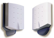
Communications and data transmission antennas,
manufacturing and development of communications
antennas for Wireless LAN, ISM band, and small cell
applications

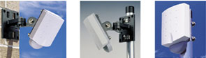
ORiNOCO
OR (Outdoor Router) Antennas & Accessories
ORiNOCO OR antennas
provide for good transmission distances between two or
more buildings. Available for directional
configurations (point-to-point), omni-directional
configurations (point-to-multipoint) and mobile
outdoor roaming configurations (for mobility within a
cell).
IQUPS If you are a systems integrator, installer, engineering procurement contractor or an electrical contractor
We will work with you to design a Solar - Fuel Cell and or Wind power system for your project some applications Business - On-Grid Commercial Buildings and Off-Grid Industrial Remote electricity anytime anywhere!.
Businesses - Government Agencies and homeowners around the world are using OkSolar systems Integrated systems Solar, fuel Cells and wind energy.
Applications:
Commercial - Industrial - Disaster Relief - Military and Residential AirportIQ UPS Airfield Power Backup Electrical
Communication infrastructure(Local and Federal Government)
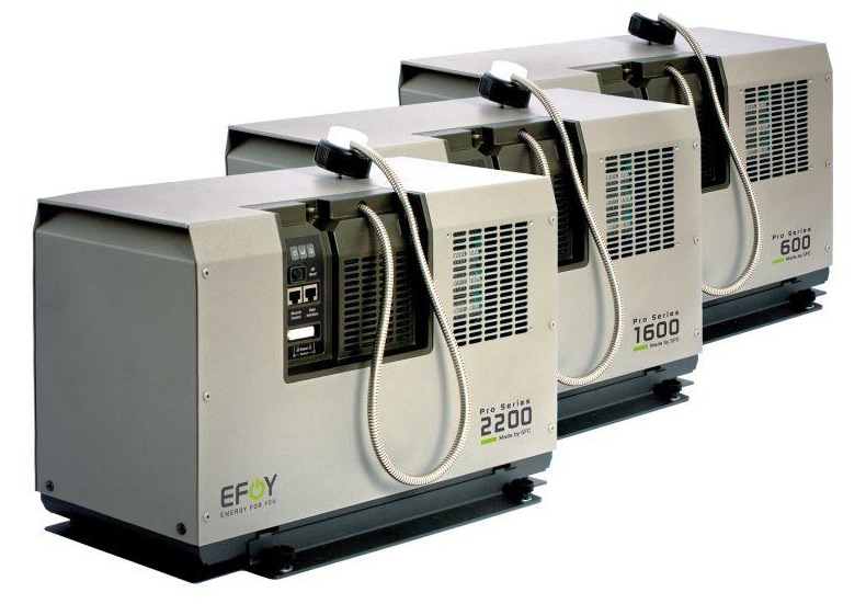
Base Stations for Mobil Networks that can run on Solar, Wind and Fuel Cells.IQ UPS Base stations cut diesel usage by 75 percent. IQUPS.com has designed a base station for mobile networks that would run on sun, wind power and fuel cells. Gas Stations (Powering gasoline pumps during a power failure).
Hospital EMS: IQ UPS Hospital Power Backup Electrical ( Emergency Power Back-up for Hospitals ).
Rail Roads: Railroad crossing signals backup.
Traffic intersections: backup power for critical LED traffic light intersections.
Solar Trees Arrays We Delivered On-Site For Fast Plug and Pay Installation Solar Tree structure are designed for the following applications: Shading vehicles from the sun and at the same time generate Green energy. Facilitate the creation of infrastructure for electric vehicles.
Traffic Application:
-Keeping Traffic Moving When The Power Goes Out Item#1608450 Portable Solar Powered 120 volts 60Hz. or 230 Volts 50 Hz, Portable Solar Powered 220 Volts 50 Hz, Portable Solar Powered 230V 50Hz, Portable Solar Powered 220Volts 50Hz pedestrian signals, A 120 or 240 V, 100 amp, single-phase IQUPS.com transfer panel is used to activate the generator at the loss of power. According to IQUPS, the generator assumes the full load in seven seconds. When utility power is restored, the generator shuts off and signal operation is automatically returned to the normal power source. "The IQUPS1800 will completely run the intersection stoplights," said general manager for the DOT. "Other backup systems will put the lights to flashing red. When the generator kicks in on the IQUPS1800, the lights will fully function for 25 to 40 hours, depending on the load at the intersection. When power is restored, the system returns to utility power and the traffic signals do not need to be reset." Battery Backups Prevent Accidents at Critical Traffic Signals Additional Applications Being Taken for More Intersections Keeping Traffic Moving When The Power Goes Out Portable Solar Power 120 Volts 60 Hz or 230 Volts 50Hz, Traffic Portable Solar Power 120 Volts 60 Hz Thanks to new IQTraffiControl.com energy-efficiency technology, different Cities, towns and counties will keep their traffic signals safely operating even if the electricity goes out, and other local governments. Intersections have been converted to new LED signal lights utilizing more efficient, LED (light emitting diode) lamps. The new lamps cut the amount of electricity used by each light from as much as 150 watts to between 10 to 25 watts. Because LEDs use so much less electricity, it is now technically possible to provide battery backup power to alike. We also Have Fuel Cells Traffic Backups.
IQ UPS Traffic Back-up Standby Power Generation.
- Battery backup systems for LED traffic Signs -
IQUPS Battery Backups Prevent Accidents at Critical Traffic Signals Increase the public safety and reduced traffic congestion by allowing traffic lights to function even during a power failure. A typical traffic signal intersection experiences eight to ten local power outages annually. With battery backup 3 power, some or all the traffic control signals can continue to operate. This seamless switchover to battery power increases public safety and eliminates the need to dispatch police or other service personnel to direct traffic. If all traffic signals were converted to LEDs, the battery backup system would allow full operation of the traffic signals during a power outage, thus alleviating traffic congestion.
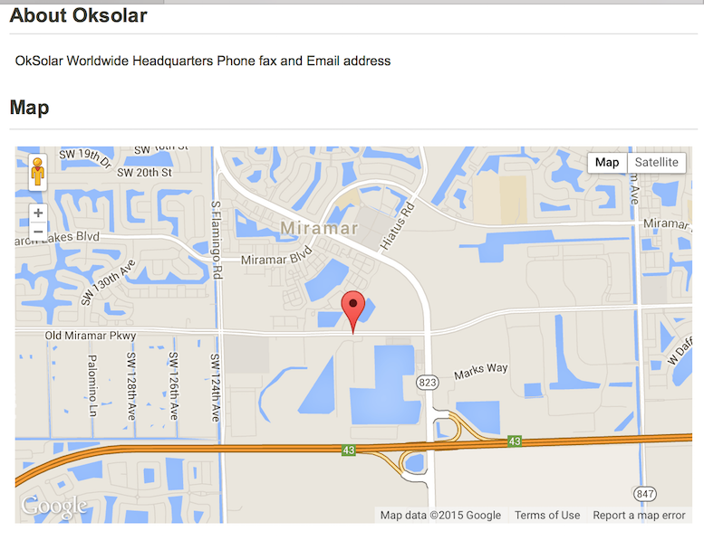
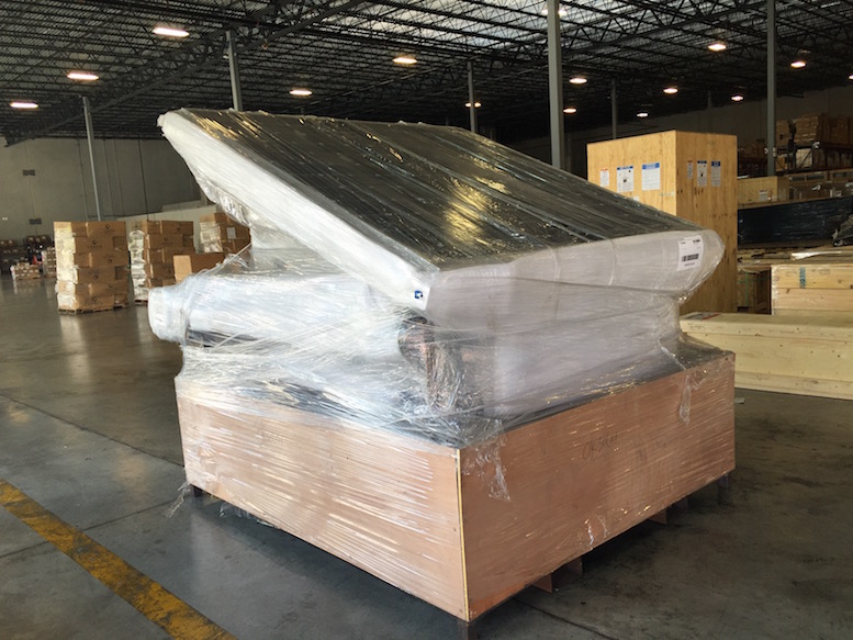
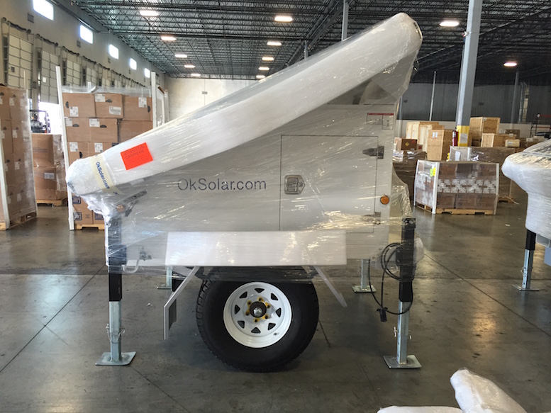
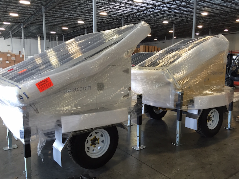
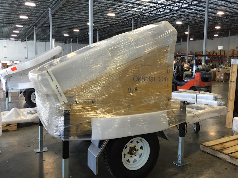
OkSolar.com Affiliate
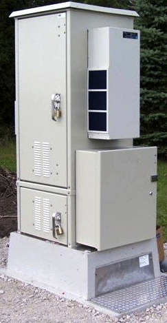
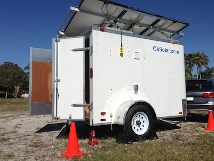

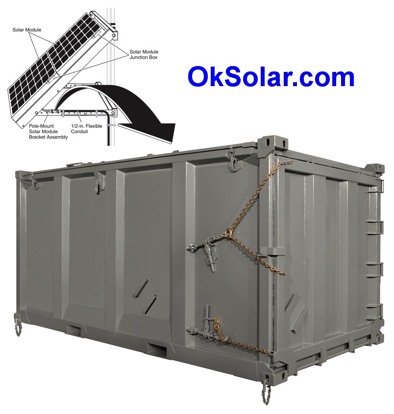

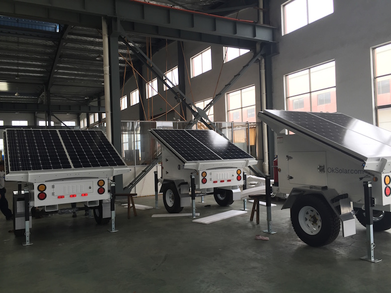
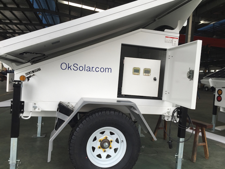
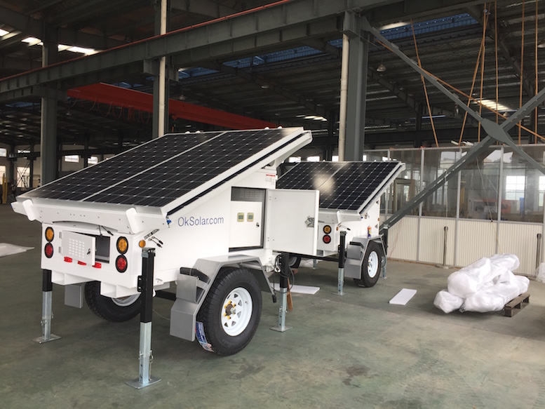
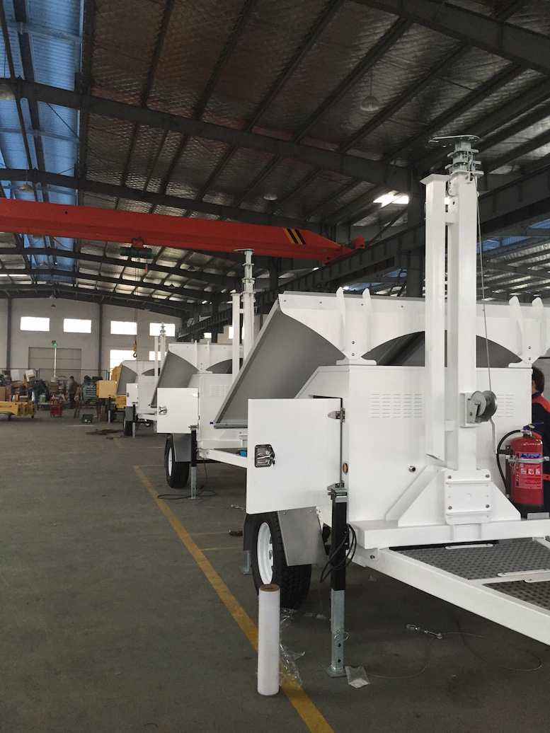
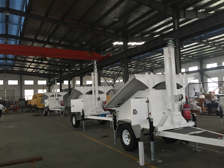
Sample Ready to ship unit


 Note:
To view the above PDF documents, you will need the
free Adobe Acrobat Reader
Note:
To view the above PDF documents, you will need the
free Adobe Acrobat Reader
Inverters, Inverter/Chargers, Smart Battery
Chargers, Emergency Backup Power, Tripp-Lite,
tripplite, tripp lite, exceltech, iota, Outback,
Inverters,Vanner, Sunny Boy, trace, xantrex, AC
Inverters and Accessories !